Microcontroller Class D Amplifier
5 Feb 2012
This article is about an obsolete version of the amplifier. For the new revision, go here.
Class D amplifiers are very efficient and could be simple to build. They operate the power stage in a binary mode and pass the delivered pulse train through a low-pass filter (which might involve the speaker itself) to filter all frequency components introduced by the switching of current.

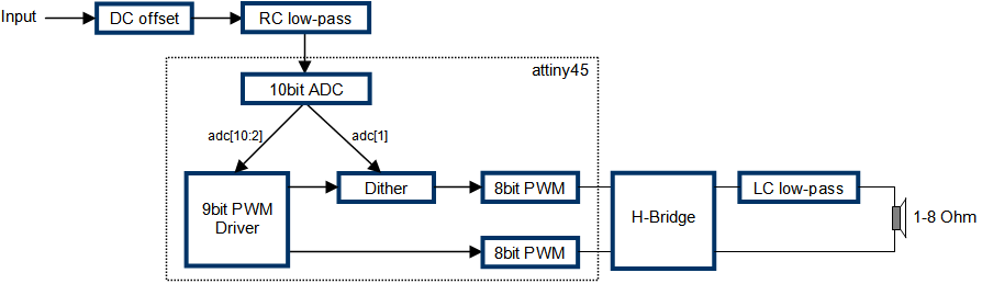
I designed a 70W bridged amplifier based on the Atmel Tiny (attiny45) microcontroller. Vcc is 12V and it requires no heat sink, nor has a feed-back loop of any kind. The output power is limited by 2 factors:
- Precision in the digital domain. Making the gain very high will hurt quality at lower levels.
- Isd of the power MOSFETs. The ones I had are rated at 6A, potentially delivering P = I^2 R = 144W at 4 Ohm or 72W at 2 Ohm..
I used the hardware ADC and the 2-channel 8bit timer as a PWM. Since we get the full 8-bits of precission only at full power, the sound quality at quiet levels was originally very poor - for example, at 1% power, we get less than 2 bits! I implemented 2 tricks to mitigate the problem:
- Non-symmetrical output signals. Since different PWMs are driving the 2 halves of the H-bridge, they don't have to be completely out of phase. Bit adc[2] from the figure below is sent only to 1 PWM.
- Dither. Dither was used in 8bit graphics to exploit the fact that the eye averages neighboring colors. Apparently it works very well with audio. Disabling this block noticeably reduces the audio quality.
The PWM driver and the dither block are implemented in the timer interrupt handler:
ISR(ADC_vect) {
    static u8 last_error;

    s16 adc     = ADC;
    s8 val1     = (u8)(ADC >> 2) - 128;
    u8 val2     = adc>>1 & 1;
    u8 error    = adc & 1;
    u8 dither   = error & last_error;
    last_error  = error - dither;

    DACN = 128 - val1 - dither;
    DACP = 128 + val1 + val2;
}
where DACP and DACN are the two PWM registers.
The DC offset stage is just a decoupling capacitor and a trimmer. The low-pass filter that follows is required because my laptop produces
a supersonic ripple at the headphone jack. It comes from the power brick and transfers
all the way to the audio output.
The H-Bridge on the output side is what people traditionally use to drive robot motors. It suits our purpose well and additionally is always in a safe state in case the CPU ever hangs.
I implemented the circuit on a prototype board, which I power from a computer power supply. Functionally it works very well without producing any heat. It drives my 3 front speakers either in parallel or in series.
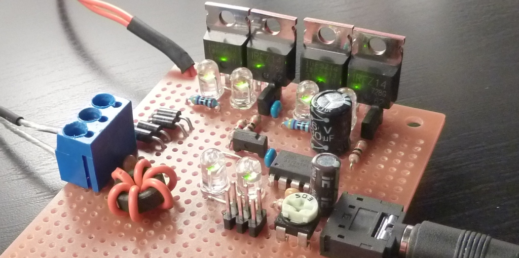
The LEDs are all functionally required - I use them as zener diodes.
The following links contain a picture of the schematic, eagle schematic + C source code and a more artistic pic.
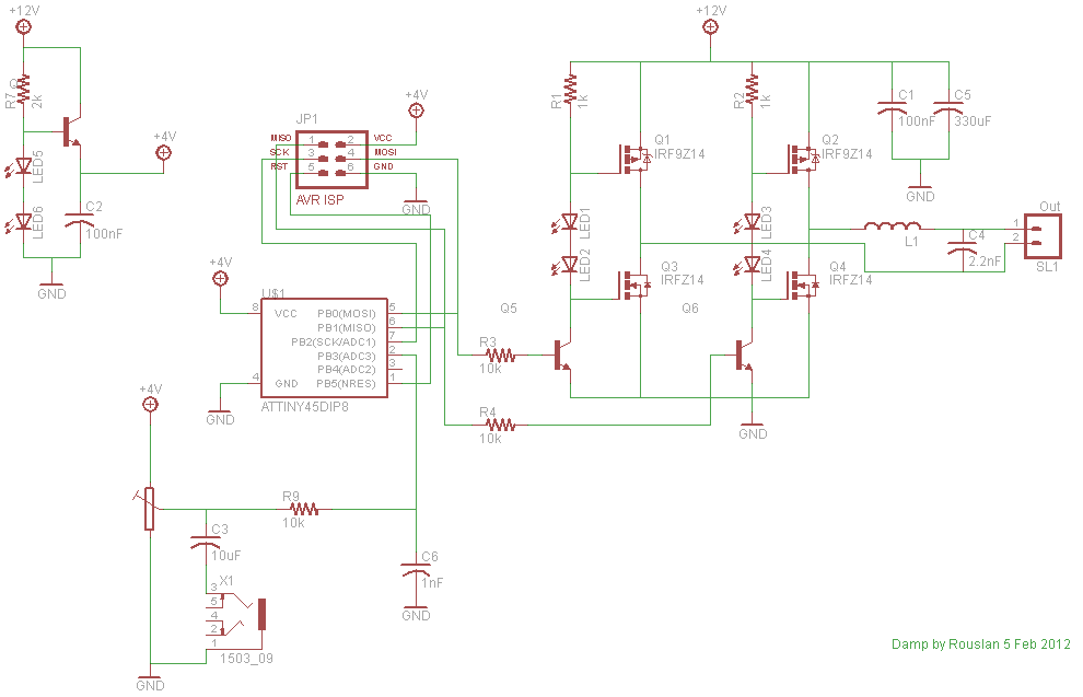
Choose the appropriate voltage regulator for audio input sensitivity, ie. 78L33 for 3.3V peak-to-peak input. I found the ATtiny45 internal voltage references to be too noisy and thus I used Vcc as ARef.
Comments for Microcontroller Class D Amplifier
ARV on February 6, 2012, 3:10:38 am EST
What are the parameters of quality of the amplifier?
Rouslan on February 6, 2012, 3:20:05 am EST
I have no means of measuring THD. My guess is <10% at 1W, much less at higher power. It sounds alright to the ear.
ARV on February 6, 2012, 4:19:36 am EST
I want to put a translation of an article on the site http://www.simple-devices.ru together with my comments and additions. You give your permission? Can I use your photos and pictures?
Rouslan on February 6, 2012, 5:09:09 am EST
Sure, I'd be happy too. Just link back to my site and give proper credit for the design.
Ross on February 6, 2012, 5:49:03 am EST
Hi. Nice design. What type are transistors Q5 & Q6? What is value of L1?
Rouslan on February 6, 2012, 5:55:58 am EST
Thanks! Q5 and Q6 are 2SD636. I made L1 experimentally. Originally, I had about 5x the number of turns and the signal came out distorted (not just dull).
simma on February 6, 2012, 10:20:43 pm EST
I notice six LEDs, whereas the circuit shows only four. Please explain. Congrates on the simple effective design (I watched the video).
Rouslan on February 7, 2012, 2:01:39 pm EST
LED1 and 2 on the schematic are each 2 LEDs in series. I originally had them blue which I replaced with green. The lower on-voltage introduced a slight crossover where the 2 FETs will be on during switching. I will update the schematic. Thanks!
Liubo on February 18, 2012, 5:27:15 am EST
Wow! It's great work!
Rouslan on February 20, 2012, 2:01:39 pm EST
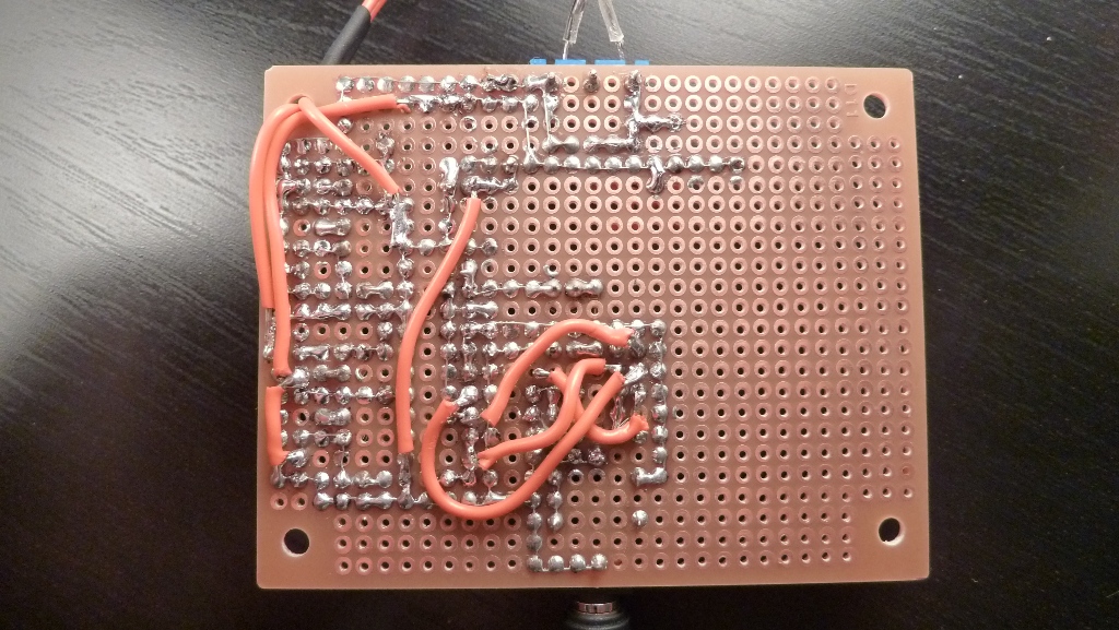
Due to a server crash I've lost several comments. There were 2 requests for the back side of the board. Here it is.
Amin on January 1, 2013
Hi, very good. how didn't you use Moffet driver? is that full bridge or half? could you please provide us with the graph of the level shifter output. that must be PWM form btw +12v and -12v . am I right?
Julian on March 31, 2013
Hi ! I like your amplifier. What type of transistor did you use for the psu part of the schematic and at the output of the MCU?
Nikolamarkovski on February 7, 2014
Genius. Make your next project about 150-200 W. Filters is something you have to be very seriously considered then but I hope you'll manage. You'll make us all happy.and no need for 12 v supply , just use 40+40 to 80 +80! By the way it's easier not to make H-bridge.Use some strong mos-fets and (again, tinkering with the filters might get very tricky. Great Respect and call me about it...
amita singh on March 23, 2014
plz give me full information class d amplifier like pcb layout , circuit diagram, making process ,how to implement in pcb?
dang on April 18, 2014
In my country they don't have the irfz14 and irf9z41 so can i replace those fet by the irfz44 or irfz34, if don't what kind of fet which i can replace? Please help me (sorry for my bad english)
d ang on April 18, 2014
In my country don't sell attiny 45, they just have attiny 2313 and attiny 13, other avr is the at mega 8, 16, 32, 88 which MCU i can use and if i use that MCU will i have to rewrite the command and how i rewrite it ? Thank you (and sorry for my poor english)
vrnrfelqhg on October 27, 2014
nMj6yx <a href="http://ohjmhxoswqeq.com/">ohjmhxoswqeq</a>, [url=http://ynftnnxbqclq.com/]ynftnnxbqclq[/url], [link=http://jrzcxiyuncgg.com/]jrzcxiyuncgg[/link], http://zlikphzciqie.com/
malarvannan on December 21, 2014
hai. your project is very good .i try to this please help me. are you send hex file to me? please. thank you.
Bruno on January 19, 2015
Hello, nice project, good quality amplifier. It seems to work very well. Where I live I can get IRF9Z20 (PMOS but with a bit higher gate capacitance) or IRFZ44N (NMOS but higher Gcap). I tried to bulid a push-pull amplifier with them but they started to heat up when they started to switch. Both them were driven by a comparator and a CMOS inverter (to decrease rising and falling times). I have a integrated complementary MOS pair with low gate capacitance and they can drive 3A and 2.3A. Can VCC be increased to get higher power? How high the efficiency is at 1 and 2 ohm load? What's the inductor value? I see you made it yourself, how did you do it? Do you have a code diagram so I can program it in PIC or freescale MCUs? Thank you in advance. Bruno.-
Oleg on August 31, 2015
Hi,Rouslan. How about fuse of ATTINY? Thanx.
A.P on September 8, 2015
Hello, what fuses do i choose ?
Oleg on October 8, 2015
No,no) Which fuses i must set and which no?
Jody on November 5, 2015
Hi Rouslan ,very cool Project. It motivated me to build a 2000W Dclass Amp using a 32bit Processor,my question is, how do you get rid of the Hissing/humming when no input is connected with out compromising on top frequencies? the best way is to change the value of C6 in your circuit but this does affect top end frequencies (Altho the noise is comming from the ADC it seems) im using the same topology @ 270Khzs PWM frequency sampling at 75k per second